
Hello my fellow hackers! Today we’re going to be introducing a topic we should’ve covered long ago, networking. Having an understanding of networking gives us a better understanding of how computers interact with each other. If we understand how these systems communicate over the network, we can better manipulate parts of the network to our advantage. Things such as routers and switches allow us to reach other parts of the network, and learning to manipulate such devices could allow for greater access to the network as a whole. The first couple of articles in this series will be all about the basics. We’ll start here with the OSI model, and work our way up. Once we’ve covered the OSI model, we’ll begin to discuss different network protocols in depth, exploring what they do, and how to exploit them. So, without further adieu, let’s talk about the OSI model!
The OSI Model
The OSI model is a model that breaks down network communication into seven layers. Each layer represents another set of functionalities that are used to get data from point A to point B. ![]() The act of data moving up and down the layers of the OSI model is known as encapsulation and decapsulation. Data being encapsulated moves down the OSI model, while data being decapsulated moves up the OSI model. This representation makes the most sense when analysed from the bottom up, so that what we’ll do.
The act of data moving up and down the layers of the OSI model is known as encapsulation and decapsulation. Data being encapsulated moves down the OSI model, while data being decapsulated moves up the OSI model. This representation makes the most sense when analysed from the bottom up, so that what we’ll do.
Layer 1 (Physical Layer)
Layer 1, the physical layer, is very simple. The physical layer is the actual media that the data moves across. Whether it be fiber optics or standard ethernet, the physical layer is the physical media on which our data is moving. For an example of a layer 1 networking device, we’ll take a look at a long out-dated piece of networking technology, the hub. 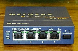 A hub is a very old device that was originally meant to create small LANs. It works by listening for the electric pulses coming into any port, and replicates those electrical pulses out all other ports, effectively passing the data. Since it replicates all pulses out all other ports, this is considered a layer 1 device.
Layer 2 (Data Link Layer)
Since layer 1 is the physical media, it’s easy to think of layer 2 as a sort of point to point connection. A single node on a network connects to another node, fragmenting, transmitting, and reassembling data as it is passed through the physical layer. 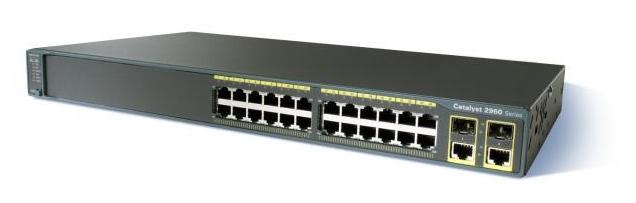 The above networking device is a switch. It is primarily used to provide access to the network for the hosts. A switch may serve the same basic functions as a hub, but it’s much smarter in the way it goes about it. Instead of replicating data out all ports, switches send data to the port they are destined for. Imagine it like this: if our NIC connecting to the switch port is layer 2, then the switch can look at all the “point to point” connections it has to decide where data should go. This is what classifies the switch as a layer 2 device.
Layer 3 (Network Layer)
So, if our layer 2 is a set of point to point connections, our layer 3 can be thought of as the functionality that allows us to send data to and from these groups of connections. 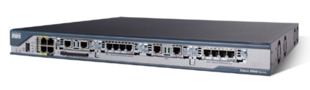 The above device is a router, which is used for routing information between networks. Here at layer 3, IP addresses are used to identify nodes on a network (at layer 2, a MAC or burnt-in address is used). Since IP can be used to represent a node on a network, routers generally have more than 1 IP address and reside on more than 1 network. This allows them to pass data between networks, such as a home network and an ISP network.
Layer 4 (Transport Layer)
Layer 4 and above gets slightly different than the other layers. Yes, there are devices that operate at layer 4, such as some stateful firewalls, but most of the layer 4 functionality relies on the TCP/IP stack which is installed on all systems that access the network. The transport layer is in charge of just that, transport. There are two main protocols that live at layer 4, TCP and UDP. At this layer port numbers are used to mark where to send data to. A port in this instance is a logical interface on a computer that can either create or receive connections. For example, the SSH service runs on port 22.
Layers 5 and 6 (Session and Presentation Layers)
Layers 5 is responsible for controlling connections between systems. Not only does it start them, but it also manages and terminates them. The presentation layer on the other hand is used to convert data back and forth between being machine readable and human readable.
Layer 7 (Application Layer)
Layer 7 is the final layer of our OSI model. The application layer is just that, the application that the data being encapsulated/decapsulated serves. Whether it be DHCP, HTTP, or FTP, the data within is considered application layer data.
That does it for this one! Next time we’ll be focusing more on the layers’ roles in a network, rather than their definitions. Also, we’ll be reviewing another model in the near future, the TCP/IP model. By the end of this series we should be able to look around a network and identify what the infrastructure looks like.
Next up, we’re going to be talking about a few protocols, ARP, IP, and TCP. Understanding these protocols will give us a basis for learning about LANs, which is an important first step in networking. We’ll start with ARP, a layer 2 (data link) protocol. Then, we’ll talk about IP and TCP, protocols resting at layers 3 and 4 respectively.
Understanding ARP at Layer 2
So, to understand ARP, we need to first discuss how computers connect to an Ethernet network. Computers interface to the network with their NIC (network interface card). This card is connected to the RJ-45 (Ethernet) plug on a system.
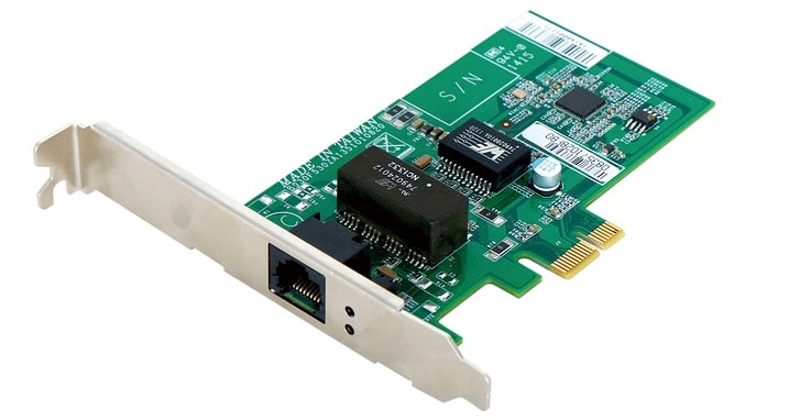 This NIC has an address on it already. This address is known as the MAC address, and its “burned” into the NIC. These MAC address are 48 bits in length, the first 24 of which are the OUI (organizationally unique identifier) which identifies what manufacturer made the NIC.
Now that we have that, let’s discuss ARP (address resolution protocol). ARP is used to resolve an IP address to a MAC address. For instance, if we have an FTP sever on our LAN, our system would use ARP to determine the MAC address of the server NIC so we can contact it on the LAN. Here’s a diagram of how this happens:

ARP simply resolves IP addresses to MAC addresses for communication over LAN. If we open up wireshark, we should be able to see the ARP traffic coming to and from our system:
![]()
Understanding IP and TCP
IP (internet protocol) is what allows us to encapsulate data to be transported over layer 3, which sounds fairly redundant but is still an important thing to remember. IP also allows us to give, maintain, and route between IP addresses and address ranges, which grants us the ability to segregate networks logically without have to separate them physically.
TCP is a transport layer protocol that is used to reliably send data from point A to point B. There are a couple protocols which transport our data (TCP and UDP specifically), and they differ from each other widely. For now we’ll only be covering TCP. TCP uses port numbers to differentiate services running on a system, such as port 80 and 443, for HTTP and HTTPS. When TCP attempts to make a connection, a handshake occurs. This is known as the TCP three-way handshake, and looks like this:

It starts with a TCP packet marked with the SYN flag (SYN is short for synchronize). If the destination device has a service running on that port that is accepting connections, it will respond with another packet marked with the SYN and ACK (acknowledge) flags (a SYN in response to ours, with an ACK to confirm its in response to us). The handshake ends with us sending a packet marked with the ACK flag to the destination device to acknowledge their SYN-ACK.
Once the handshake is complete, our connection is considered established until it is dropped or terminated by either side. This connection can now be used to transport data between our two systems reliably. That means that TCP can recognize corrupt or missing data and request a re-transmit of that data.
Putting it Together
Let’s wrap this up with a little hypothetical to bring it all together. Let’s say you have a system on a LAN with a default gateway connected to the internet. If you point your web browser to a site on the internet, your system will first use ARP to find the MAC address of the default gateway (if it doesn’t already know it). Then, once the MAC address is found Ethernet frames will be transmitted across the network to the router, which will be reassembled to reveal that its a TCP SYN packet destined for port 80 of a web server. The router will forward this packet, and all packets related to it, in and out of the LAN. Once the TCP three-way handshake is over, our system will send an HTTP GET request to the web server. Upon receiving the request, the server will response to our system with the requested web page packed as application data in more TCP packets.
There we have it! Hopefully that made some of this click a little better.
So now that we’ve covered ARP, IP, and TCP and covered how these protocols relate to the operation of a LAN. Now, we’re going to be going over a few more protocols, as well as introducing a new model (like the OSI model but a little different). We’ll start with introducing the new model, the TCP/IP model. Then we’ll discuss the DHCP and UDP protocols, their relation to either model, and their role in the network. So, let’s get started!
Understanding the TCP/IP Model
If you remember back to the first article in this series, we talked about the OSI model and its different layers. Well, the TCP/IP model is a lot like that, except that it’s layers are different. Whereas the OSI model has seven layers, the TCP/IP model has four. The TCP/IP model layers are as follows:

The layers of the TCP/IP model, from bottom to top, are comprised of the network interface, network, transport, and application layers. The network interface (sometimes called the network access) layer corresponds to the physical and data link layers of the OSI model. The network and transport layers are the same for both models (the network layer of the TCP/IP model is sometimes referred to as the internet layer). Also, the application layer of the TCP/IP model is equivalent to the session, presentation, and application layers of the OSI model collectively.
There isn’t really a distinct advantage to using one model over the other, but both are used throughout the IT industry, so knowing both can be a big help. Now that we’ve covered the TCP/IP model, let’s get talking about some protocols. We’ll start with UDP, then we’ll discuss DHCP.
Understanding UDP
If you remember the last article, we talked about TCP, a transport protocol used to reliably send and receive data over a network. As we discussed, TCP is reliable and will re-transmit if needed. UDP (user datagram protocol) on the other hand is neither reliable nor does it check the data integrity (integrity is the concept that data should not be damaged or altered, and that we should be able to tell when it has been).
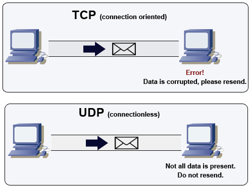
UDP is unreliable, which isn’t necessarily a bad thing. UDP doesn’t even have acknowledgements, which TCP uses in conjunction with checksums to determine if data has been corrupted during delivery. Due to this lack of reliability, UDP is much faster at transmitting data. This makes it perfect for things like voice and video, which are extremely sensitive to delay.
Understanding DHCP
DHCP is a very important protocol to understand, as just about every network makes use of it to a certain degree. DHCP stands for dynamic host configuration protocol, and its in charge of delivering IP information to new hosts joining the network. The information that DHCP provides is the hosts IP address, the subnet mask, the default gateway, and DNS information. To access a LAN, a client must have at least an IP address and a subnet mask.

DHCP relies on the DORA process to deliver IP information to joining hosts. The DORA process consists of discovery, offer, request, and acknowledgement. Its a fairly simple process, first the client sends out a broadcast looking for DHCP servers. Next, if a DHCP server identified the discovery attempt, it will send an offer to the client. Then, the client submits a request to the DHCP server, confirming their accepting of the offer. The DHCP server responds with an acknowledgement and everything is good to go! This protocol allows for easily adding hosts to a network without having to configure IP information for all of them. Its worth noting that DHCP is normally only used for host devices, things such as servers and network infrastructure usually use static IP addressing.
That does it for this one! Hopefully that help reinforce what we learned last time about LAN basics. Next time we’ll introduce routing and switching, and how their respective devices work.